

Series CF ClearFloater™ Flotation Separator
Request More InformationSIZING SERIES CF CLEARFLOATER™ FLOTATION SEPARATOR
| Model | ClearFloaterTM Wastewater Flow Rating (gpm) a | ||
| ClearFloaterTM | SAFTM Generator | Recommended Minimum | Recommended Maximum |
| CF25 | F8 | 10 | 30 |
| CF50 | F8 | 20 | 100 |
| CF125 | F8 | 50 | 200 |
| F25 | 125 | 250 | |
| CF250 | F25 | 200 | 350 |
| F50 | 250 | 500 | |
| CF500 | F50 | 350 | 700 |
| F100 | 500 | 1,000 | |
| CF1000 | F100 | 700 | 1,400 |
| F200 | 1,000 | 2,000 | |
| CF2000 | F200 | 1,400 | 2,800 |
| F400 | 2,800 | 6,000 | |
| CF3000 | F400 | 4,000 | 8,000 |
a. Maximum flow rates are dependent on constituent concentrations. Excessively high concentrations may require testing to size equipment.
SERIES CF CLEARFLOATER™ FLOTATION SEPARATOR DIMENSIONS
| MODEL | FLOTATION | DIMENSIONS | PIPE SIZE (in.) | |||
| AREA (sq. ft.) | W | L | H | A | B | |
| CF50 | 8 | 5' | 9' | 7' | 3 | 3 |
| CF125 | 17.5 | 6' | 10' | 8' | 4x(2)3 | 6 |
| CF250 | 35 | 8' | 12' | 9' | 6x(2)4 | 8 |
| CF500 | 72 | 9' | 18' | 11' | 8x(2)6 | 10 |
| CF1000 | 144 | 12' | 25' | 13' | 12x(2)8 | 12 |
| CF2000 | 304 | 12' | 44' | 13' | 14x(2)12 | 16 (2) |
| CF3000 | 432 | 12' | 60' | 13' | 18x(2)12 | 18 (2) |
a. Maximum flow rates are dependent on constituent concentrations. Excessively high concentrations may require testing to size equipment.
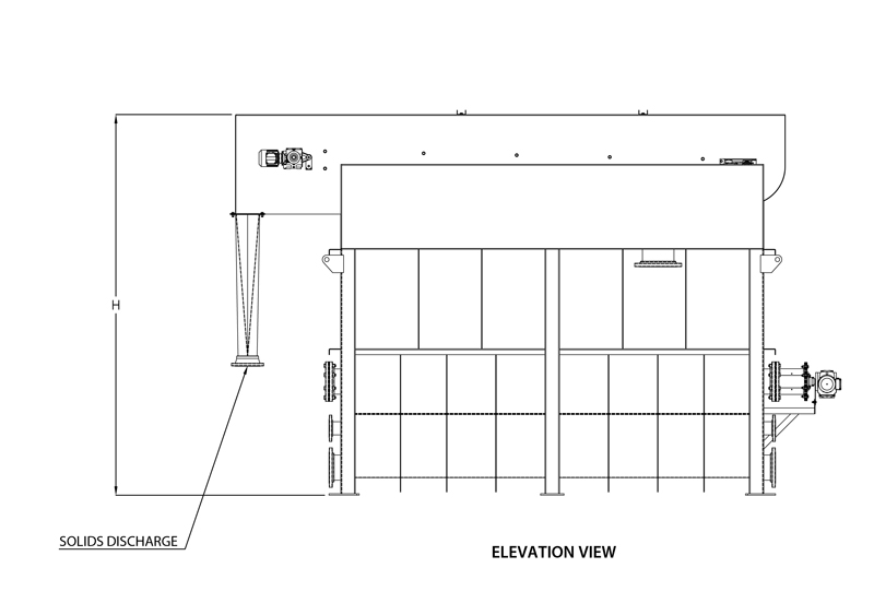

FLOTATION TANK DESIGN
The Series CF design has been developed to realize the full advantage of the extremely high rise velocities and stable float characteristic of flocculated solids having Suspended Air® bubbles attached. The inlet passes through an agitated flocculation chamber and flow to the flotation area is distributed evenly across the tank length. The skimmed surface is longer that it is wide. The solids are skimmed off immediately after reaching the surface.
The unique durability of the float typically allows sufficient dewatering without allowing a mat of solids to build up. However, every ClearFloaterTM Flotation Separator skimming system is equipped with a variable frequency drive (VFD) motor for controlling the speed of the skimming rake and an on/off delay timer to allow for more dewatering should that additional effort be required. Skimmed solids area scraped up an inclined beach section to the discharge chute. Clarified effluent passes underneath a deep baffle, overflowing a full-width adjustable weir to the effluent receiving box.
EQUIPMENT FEATURES AND OPTIONS
Tank and Support Materials
304 Stainless steel, minimum 12 gauge, welded construction.
Flocculation Chamber
Mechanically agitated compartment within the flotation tank, mixer shaft direct- driven by a variable speed gearmotor. Provides for effective blending of Suspended Air® Emulsion and additional polymer with influent coagulated/flocculated wastewater.
Mechanical Skimmer
Chain and flight, stainless steel fights and shaft, thermoplastic sprockets and pintle chain, with the drive sprocket direct driven by a variable speed gearmotor. Timed on/off cycle be supplied as an option.
How Did It All Begin?
The first applications of SAF® were in the food processing industry because the company was located in California’s agricultural Central Valley and there was a need for treating wastewater from a variety of food processors. Since then installations have expanded to other industries that formerly relied on the traditional DAF approach. The Suspended Air® Flotation Process can be and is applied in any application where physical/chemical separation via flotation is a viable alternative.


